Optical Time Domain Reflectometry (OTDR)
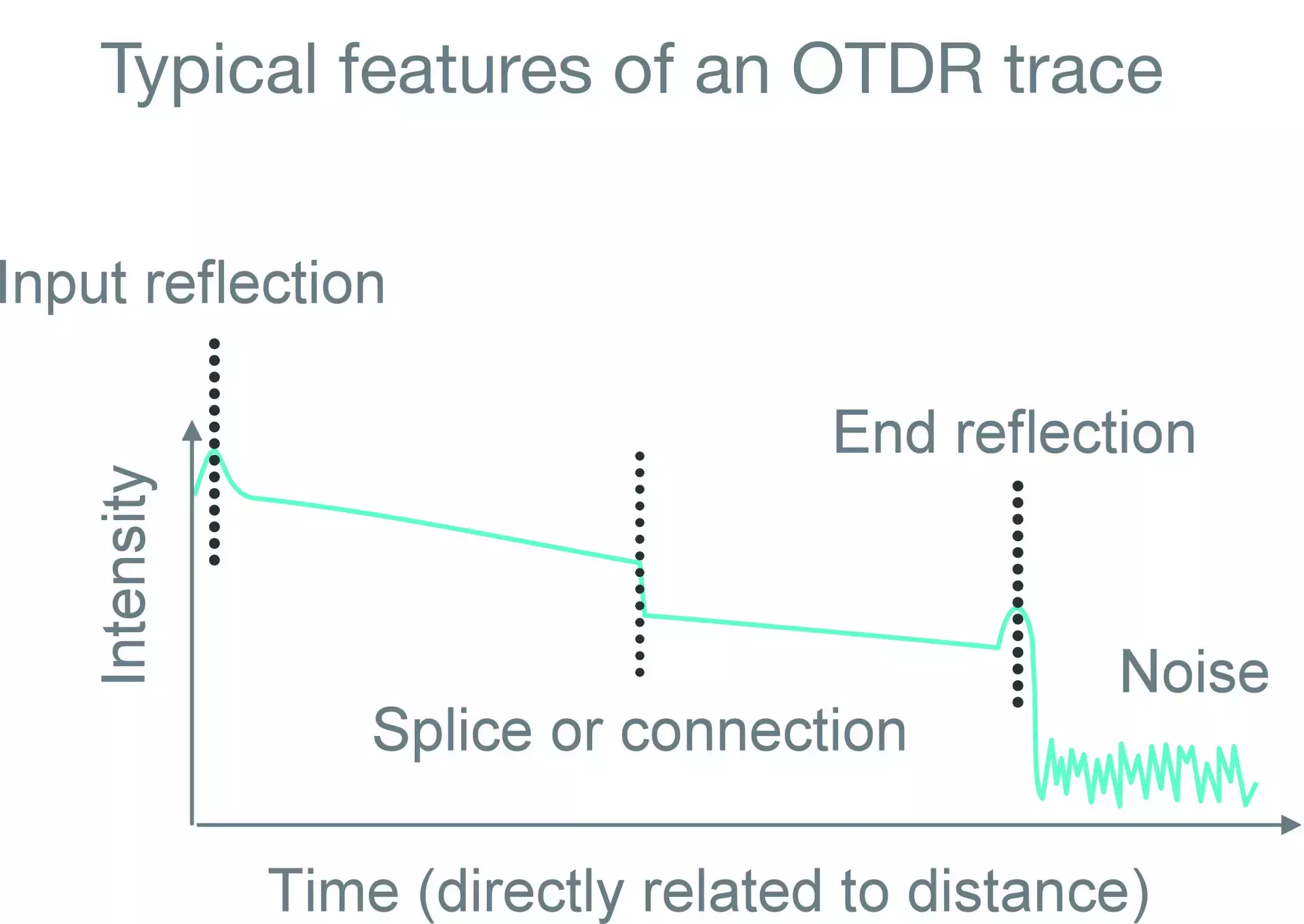
A method of investigating losses, splice features and defects along a fiber optical path. The Rayleigh scattering of the fiber creates a signal that propagates back along the fiber towards the source (backscatter). An OTDR meter sends light pulses into the array and measures how much light comes back with time. The light from the far end will take longer to return to the detector, so it can be determined how long the fiber is. If there are any losses or joins, light will be lost here and less light will be returned, putting a step in the trace.
Features along the fiber length can be located by looking at the level of light returned. The slope of the measurement from one part of the trace to the next shows the loss (usually dB/km) along this region. In the example below, the trace is steeper before the join than after; indicating this part of the fiber has a higher background loss. The flat cleaved end of a fiber creates a (Fresnel) reflection, so is evident by a peak in the trace – here the join does not show a peak, so is more likely to be a splice than a connector, though it could be perhaps an APC connector (specially angled to reduce back reflections).

Commercial OTDR units can interrogate the fiber at a range of wavelengths, 1550nm and 1310nm being common choices for telecoms systems. Sometimes it can be of value to assess the background loss with an OTDR operating at other wavelengths, for example around 1200nm where rare-earth doped fibers have little ionic absorption; avoiding the telecoms wavelengths where they do.
Related Terms: Brillouin Scattering, Connector Types, Fresnel Reflection, Raman Scattering, Rare-Earth Metal, Rayleigh Scattering