Fiber Optic Current Sensors & Optical Current Transformers
The basic principle of Fiber Optic Current Sensors (FOCS) and Optical Current Transformers (OCTs) is to measure polarization rotation due to the Faraday effect. The Faraday effect is the rotation of the polarization state of light, β, when it passes through a magnetic field, B, induced by an electrical current. The larger the electric current, the greater the magnetic field and hence the larger the polarization rotation.
FOCS/OCTs offer significant advantages over traditional current sensing technologies; the sensor element is naturally decoupled from the voltage line, there is minimal electrical interference on the signal line, they offer extremely fast response times with high measurement accuracy, the size and weight of the sensors is reduced in comparison with existing technologies and they do not explode during catastrophic failure, unlike oil-filled electrical insulation towers.
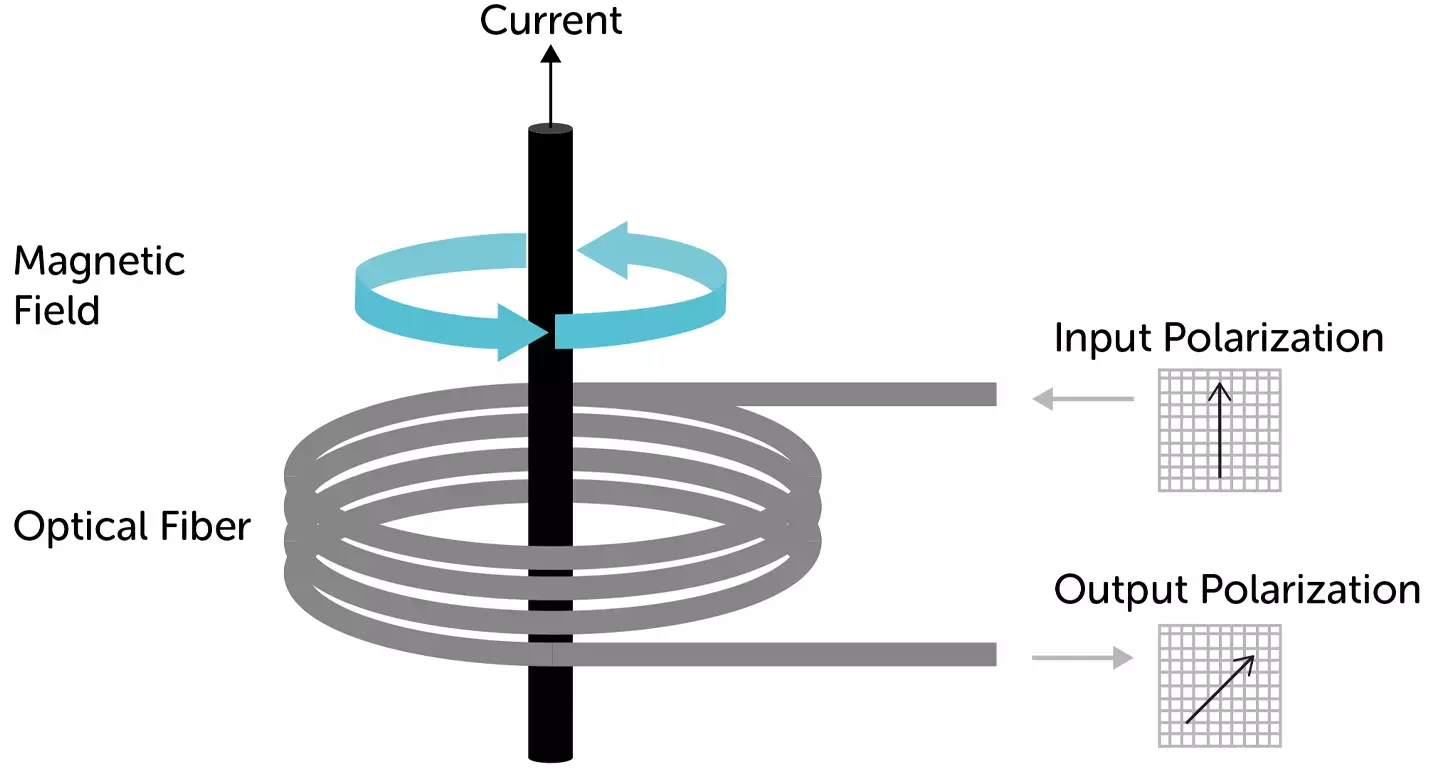
Figure 1. Representation of rotation of light polarisation in a fiber optic current sensor due to the current going through the conductor
Fibercore has developed a range of optical fibers designed specifically for use in FOCS. This includes the sensor element fibers Spun HiBi and Spun LoBi fibers, as well as supporting component fibers such as ZingTM Polarizing Fibers (HB-Z), Standard PM Fiber (HB), Telecoms PM Fiber (HB-T) and PM Gyro Fiber (HB-G) for delay coils and quarter wave plates.
The fibers can be used in various deployments from simplistic low sensitivity, low accuracy, Spun LoBi systems through to high sensitivity, high accuracy, circularly polarized, Spun HiBi systems.
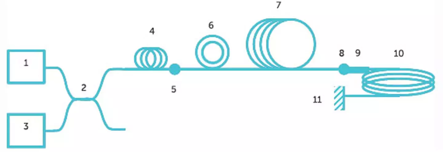
Figure 2. Optical schematic for a high sensitivity fiber optic current sensor, showing (1) broadband erbium doped light source, (2) coupler, (3) photo detector, (4) polarizer, (5) 45o splice, (6) fiber modulator, (7) 900m long delay coil, (8) 45o splice, (9) quarter wave plate, (10) 16m of spun HiBi fiber, (11) mirror.[1]
Historically, FOCS system manufacturers attempted to manufacture current sensors using standard telecoms fibers. However, the inherent random birefringence within these fibers causes significant limitations on the sensing accuracy. Techniques were developed to twist the fibers, which ultimately created mechanical failure when the fibers were exposed to rapid thermal changes due to the torsional forces exerted on the fiber. Alternative methods of stripping the coating off the fiber and annealing the bare glass were developed. Nevertheless, due to the difficulty of stripping long lengths of coatings, poor yields and short lengths were fundamental limitations to this technique. Subsequently, spun fibers were invented where the fiber is spun during the fiber drawing stage, this creates a rotation along the length of the fiber which is locked into the fiber with no torsional force. The rotation causes the inherent birefringence effects to be axially rotated many times over the length of the sensor, averaging out the negative effects of the birefringence.
Spun LoBi Fiber
A Spun LoBi fiber is Single-Mode (SM) fiber which is spun during the fiber drawing stage, averaging out the inherent birefringence induced during the fiber manufacturing processes.
When the Spun LoBi fiber is coiled, bend-induced birefringence is created within the fiber which reduces the maximum sensitivity of the FOCS. As the coil diameter is reduced or as the number of coils is increased, the stress on the fiber cumulatively increases, creating higher total birefringence and making the measurements less sensitive [2]. Subsequently, Spun LoBi fibers are typically used in low sensitivity FOCS or OCTs, which have a large coil diameter and a relatively low number of coils.
Spun HiBi Fiber
For high sensitivity FOCS and OCTs, it is advisable to use Spun HiBi fiber. This fiber differs from the Spun LoBi fiber by having a Polarization Maintaining (PM) axis which is formed by Fibercore’s ‘Bow-Tie’ structure. By carefully balancing the spin pitch of the fiber with an accurately controlled level of birefringence, a fiber can be designed that can overcome the effect of bend-induced stress by the coiling process yet still be sensitive to the Faraday effect. Subsequently, longer lengths of Spun HiBi fiber can be used than Spun LoBi fiber, this allows more coils of fiber with smaller coil diameters to be used, giving a higher sensitivity [2]. The HiBi nature of the fiber also helps to reduce the effects of temperature and vibration.
Polarizing Fiber
It is common to use light with a single polarization state in a current sensor system. Fibercore has developed an all-fiber ZingTM Polarizing Fiber, which is capable of stripping energy from the fast axis, leaving only light in the slow axis. By having an all-fiber device, low insertion loss, small form factor, and high-reliability polarizers can be achieved. This is particularly important for any current sensor that experiences vibrations, such as any designs incorporated into switchgear and circuit breakers.
Depolarizer
FOCS commonly use depolarizers as well as polarizers. If a light source has an uncontrolled polarization state, for example, a superluminescent diode coupled into non-PM SM fiber, then it is necessary to depolarize the light before polarizing. Otherwise, the polarization state in the SM fiber can rotate, causing power fluctuations on the output of the polarizer. By splicing two PM fibers together with the stress axis offset by 45o, a Lyot depolarizer can be created. To maximize the performance of a Lyot depolarizer, it is important to choose the correct lengths of the two pieces of PM fiber. This is non-arbitrary and depends on many factors including the birefringence of the fiber, wavelength, bandwidth, and spectral shape of the light source. Fibercore’s HB series, HB-G, and HB-T series of PM fibers are ideal for use as Lyot depolarizers.
Delay Coil Fiber
Depending on the optical configuration, a delay coil can help improve the sensor signal by creating a suitable phase shift between the orthogonal linear polarization states, typically a few hundred meters of fiber is used to create the delay [1]. To maintain the polarization state, a PM fiber can be used. Fibercore offers three suitable ranges of fibers, HB, HB-T, and HB-G series. The HB fibers have a 125μm cladding diameter and the HB-G fibers have 80μm cladding. The 80μm fiber offers the advantages of higher sensitivity, reduced packing size, and improved reliability when coiled into small diameters.
Quarter Wave Plate Fiber
A quarter wave plate is used to convert linearly polarized light into circularly polarized light. This can be achieved by splicing a short piece of HB or HB-G spliced with the birefringent axis rotated by 45o. The exact length depends on the light source and birefringence of the fiber.
Erbium Doped Fiber
Erbium Doped Fibers (EDFs) can be used to make Amplified Spontaneous Emission (ASE) light sources capable of emitting broadband incoherent light. Using a broadband light source can considerably improve the current sensing stability over the temperature in comparison with using a narrowband light source [2]. Fibercore manufacture two ranges of erbium doped fibers, IsoGainTM and MetroGainTM offering a wide range of absorption rates, cladding diameters, and pump wavelengths. For high conversion efficiencies IsoGainTM fibers, such as I-4(980/125) offer the best option or for short fiber lengths and smaller packing sizes, the MetroGainTM M-12(980/125) is ideal.
References
[1] V.P. Gubin et Al, “Use of Spun optical fibers in current sensors”, Quantum Electronics, vol. 36, no. 3, pp. 287-291, 2006
[2] R.I. Laming and D.N. Payne, “Electric Current Sensors Employing Spun Highly Birefringent Optical Fibers”, Journal of Lightwave Technology vol. 7, no. 12, pp. 2084-2094, 1989