The principle of Mini/Micro Erbium Doped Fibers (EDFAs) has been known for a while and products have been on the market for about a decade. As internet speed and data rates increase, one of the challenges in the telecoms industry is the space within server rooms. Consequently, these either need to grow or equipment needs to shrink. In most cases, should twice the quantity of bandwidth be required, then twice the amount of equipment will need to be used. This is where mini and micro EDFAs come in. In reality, a normal EDFA has a coil of around >50mm diameter. With a Mini EDFA, it can go down to sub 10 mm in diameter, a dramatic reduction. Albeit a slight trade-off inefficiency, one mini EDFA is the equivalent of one normal EDFA.
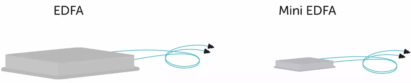
Figure 1: A ratio comparison between a normal EDFA and a Mini EDFA
What is a Mini or Micro EDFA?
The term ‘micro’ or ‘mini’ EDFA covers a broad range of form-factors, all of which are significantly smaller than the traditional 1u 19” rack-mounted ‘Blade’, which can range from a 50mm width down to the 18.5mm of a ‘plug-and-play’ XFP package. These devices typically cover the C-band of 1530 - 1565nm only and are either single or few-channel, with power outputs of 19dBm or lower. The description also covers the devices that used to be called ‘Amplets’, the business card-sized EDFAs first proposed in the early 2000s.
Impact on Fiber Design
Mini/micro EDFAs provide an exceptionally challenging environment for an Erbium Doped Fiber (EDF). Demand for greater consideration is given to fiber design/selection in four main areas:
- Resistance to Bend Induced Loss (BIL)
- Erbium Concentration / 1530nm absorption
- Mechanical Reliability / Lifetime
- Physical space available within the package
Resistance to Bend Induced Loss
Tight coiling means mini/micro EDFAs need a very small amount of space, but the fiber must be resistant to BIL and be able to sustain mechanical reliability under those really tight bends.
To improve resistance against BIL, the Numerical Aperture (NA) can be increased, which expands the guidance of the core and/or increase the cut-off
of the core so the bend loss only occurs later on. The higher NA and cut-off gives greater resistance to BIL. Depending on the intended purpose for the mini/micro EDFA, there might be a limitation to the cut-off. A cut-off needs to be Single-Moded (SM), but it is possible to get away with a moderately Multimode (MM) pump launch. A high NA variant is the I-25H, which has an increased resistance to BIL.
All Fibercore Erbium Doped Fiber IsoGainTM fibers are designed to be exceptionally resistant to BIL. Telecommunications-type fibers only have to guide and operate SM in a 60mm minimum diameter (CCITT / GR20) between 1240nm and 1600nm. Unlike telecommunications-type fiber, IsoGainTM must essentially be SM all the way from the 980nm of the pump, right up to the edge of the C-band at 1565nm. Now, if used in an XFP package, the gain-section must be coiled to a diameter of 15mm. If tried with a conventional EDF, it would simply not work. Fibercore offers a high NA variant of IsoGainTM especially to combat this problem. Coiled to a 15mm diameter it will show no measurable loss.
Mechanical Lifetime & Reliability
Coiling the fiber to the incredibly tight standard of the mini/micro EDFA specification will put a lot of stress across the fiber at the bend. The use of thick fiber has an increased stress at the bend because the pressure is intensified. This can be counteracted by reducing the diameter of the fiber, which in turn reduces the levels of stress and strengthens mechanical reliability.
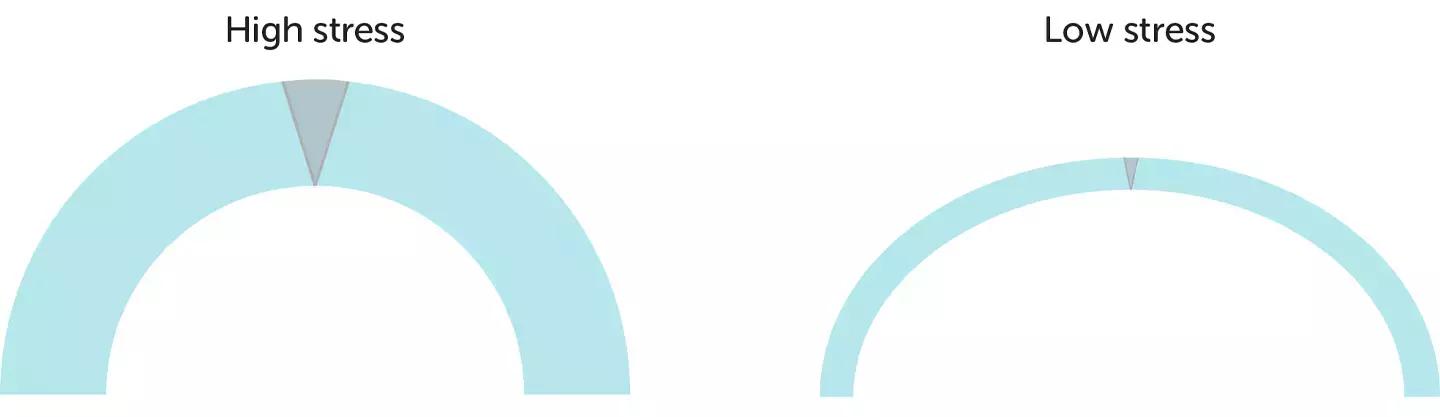
Figure 2: Stress comparison between higher and lower diameter fibers at the bend.
To further improve mechanical reliability, a supporting factor would be to use less fiber. Lessening the amount of fiber in the bend decreases the possibility of a point breaking. For example, one hundred meters in a bend has more chance of breaking than if there were only one meter in a bend. The method used to reduce the fiber length is to raise the erbium concentration, which increases the amount of absorption from the pump light per meter. The result? A similar amount of output is achieved with a shorter length of fiber, making it more cost-effective for the customer.
Fibercore can specifically design a fiber to suit the requests of each customer. Time is taken to really understand in high detail what the user needs and any additional external factors. It is a consultative and interactive process between us and the customer, including testing, feedback, and discussions. Fibercore understands the challenges of making mini/micro EDFAs and wants to provide the fiber that best fits the requirements.
We use the Modified Chemical Vapour Deposition (MCVD) process to manufacture our fibers, making it relatively easy for us to change the gain spectra. This added advantage provides a level of flexibility, which is harder to achieve for some of the competing technologies. The MCVD technique has also enabled us to effect a rapid improvement of our core efficiency, ensuring close control. This in turn means we can produce engineering samples promptly, allowing the customer or our benefit to discover additional benefits more swiftly than otherwise possible.